oriolrius.cat

Des del 2000 compartiendo sobre…

Tag: wireless

Ubuntu server as wifi AP and Mikrotik as a DHCP server

Reading time: 2 – 3 minutes

It’s important to have a very clear picture about the scenario that we’re going to configure in that case because it’s a little bit particular. This is an evolution of the previous post: Ubuntu server as wifi AP and Mikrotik as a DHCP server

schema

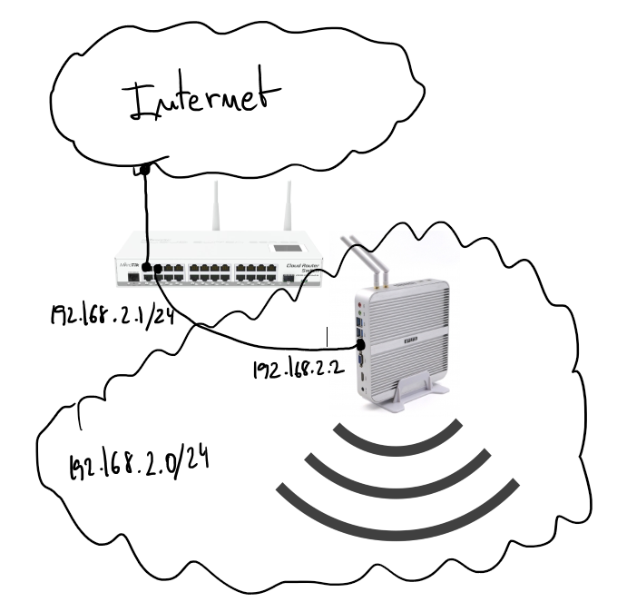
There is a server running Ubuntu 16.04 and offering wifi service as an AP. The wifi interface is in bridge mode with the ethernet port and send all traffic to the Mikrotik gateway where there is a DHCP server in charge to serve IP address to wifi clients.

Start by configuring the bridge in the Ubuntu server. File “/etc/network/interfaces”:

source /etc/network/interfaces.d/*

auto lo br0
iface lo inet loopback

#ethernet interface
allow-hotplug enp2s0
iface enp2s0 inet manual

#wifi interface
allow-hotplug wlp3s0
iface wlp3s0 inet manual

# Setup bridge
iface br0 inet static
    bridge_ports enp2s0 
    address 192.168.2.2
    netmask 255.255.255.0
    network 192.168.2.0

Pay attention on “bridge_ports” the wifi interface is not added on the list, this is because until the hostapd is running it doesn’t make sense to do that. You’ll see “bridge=br0” option on hostapd.conf which will fix that misbehavior.

Wifi AP configuration, “/etc/default/hostapd”:

DAEMON_CONF="/etc/hostapd/hostapd.conf"

and “/etc/hostapd/hostapd.conf”:

bridge=br0                # bridge interface
interface=wlp3s0          # wifi interface name
driver=nl80211
ssid=the_ssid_name        # name of your network
hw_mode=g
channel=1
macaddr_acl=0
auth_algs=1
ignore_broadcast_ssid=0
wpa=3
wpa_passphrase=the_secret_key   # secret key to joing with the wifi network
wpa_key_mgmt=WPA-PSK
wpa_pairwise=TKIP
rsn_pairwise=CCMP
logger_syslog=-1
logger_syslog_level=3
logger_stdout=-1
logger_stdout_level=1

DHCP server configuration on Mikrotik:

# setting the interface address, in my case ether4
/ip address
add address=192.168.2.1/24 interface=ether4 network=192.168.2.0

# setting up DHCP on interface 4 of the mikrotik device
/ip dhcp-server
add address-pool=dhcp-pool disabled=no interface=ether4 name=dhcp-pool

# network of the DHCP server
/ip dhcp-server network
add address=192.168.2.1.0/24 dns-server=8.8.8.8 domain=your_network.local gateway=192.168.2.1 netmask=24

# IP pool used by the DHCP server
/ip pool
add name=dhcp-pool ranges=192.168.2.65-192.168.2.70

Firmware of my home heaters (Panstamp = Arduino + TI C1101)

Reading time: < 1 minute Clicking the next link you can get my github repository with the firmware of my home heaters. The code is very simple but useful as we tested last winter at home.

I know all the public documentation is not enough to duplicate my heating project. I’m so sorry but I have a lot of pending home projects to do because I have a lot of under construction things. If you need some help to understand what I have or how to do something feel free to ask.


Home heating using Panstamp (Arduino + TI C1101) and SSR

Reading time: 3 – 5 minutes

Last weekend I worked on setting up home heaters using Panstamp. Panstamp is an Arduino board with Texas Instruments radio. Next winter we’re going to control our home heater using connected internet devices like the laptop, tablet o mobile phones. In this post I only want to share some pictures about the process to install the electronics inside the heaters changing the old electronic boards with new custom ones.

The parts:

  • AC/DC transformer, outputs 5V. It’s really cheap, in this case free because I have more than 20 of them from old projects.

acdc5v_

  • A small custom PCB designed and made by Daniel Berenguer, the owner of Panstamp. Thanks again Daniel. I bought the PCBs and parts for around 10€ each one.

IMG_20130923_114830

  • TMP36 temperature sensor. It costs about 1,5€ each one.

IMG_20130923_114814

  • Solid state relay (SSR) bought in Alied Express web site for less than 5€.

ssr

The process:

I used a lot of tools, because DIY aren’t my strong hability.

IMG_20130921_141640

Double-head tape and hot-blue gun are need…

IMG_20130921_133746

because I want to use a cork base under the PSU and PCB

IMG_20130921_133723Parallelization of the last process
IMG_20130921_143116Using a cutter I got the units
IMG_20130921_143434SSR setup
IMG_20130921_164651connecting SSR, PCB and PSU
IMG_20130921_170711assembling everything on heater side panel
IMG_20130921_173937finally, mounting side panel on the heater
IMG_20130921_133547

Next weeks, I’ll come back with this subject to talk about the software part.

HTC Polaris: mantenir wifi:on quan estem en standby/suspend

Reading time: 1 – 2 minutes

Sobretot quan tinc la HTC Touch Cruise (Polaris) a la dock station i connectada via Wi-Fi amb algún dels ordinadors de casa és realment un problema que s’apagui per timeout del standy o el suspend i per molt gran que posem aquests números sempre s’apaga quan menys t’ho esperes.

Després de donar un tomb pels forums d’XDA-Developers he trobat un thread que m’ha donat la solució. Tan senzilla com modificar el registre amb aquests valors:

HKEY_LOCAL_MACHINESystemCurrentControlSetContro  lPowerStateSuspend{98C5250D-C29A-4985-AE5F-AFE5367E5006}
-change (Default) DWORD Dec to 1
HKEY_LOCAL_MACHINESystemCurrentControlSetContro  lPowerStateResuming{98C5250D-C29A-4985-AE5F-AFE5367E5006}
-change (Default) DWORD Dec to 1
HKEY_LOCAL_MACHINESystemCurrentControlSetContro  lPowerStateUnattended{98C5250D-C29A-4985-AE5F-AFE5367E5006}
-change (Default) DWORD Dec to 1
If you need to change it back, the default entry for all of them
(at least on my Cruise) was set to 4

Realment senzill d’aplicar i fins hi tot sense reiniciar funciona perfectament.

Configurant una Atheros AR5212/5213 amb Ubuntu 6.06 Dapper

Reading time: 2 – 4 minutes

La base del MPK és una Ubuntu 6.06 Dapper, doncs bé ahir vaig tenir la necessitat de configurar-hi una targeta Wifi per primera vegada. La qüestió és que la cosa em va donar una mica més de feina de la esperada. Així doncs, aquí penjo quatre notes de com posar-la en solfa ben ràpid.

Al iniciar l’Ubuntu amb l’Atheros punxada els drivers de madwifi del kernel la detecten perfectament però malgrat no em donava cap error i després d’associar-me a diversos APs amb WEP i WPA-PSK no hi havia manera d’intercanviar tràfic, sempre donava l’error de que no trobava el destí del paquet. Finalment el que vaig fer va ser descarregar els drivers de madwifi, concretament la versió 0.9.3.3. Que ha compilat sense problemes i després de borrar els drivers que inclou l’Ubuntu per defecte, s’han instal·lat a la carpeta dels mòduls del kernel. Després de comprobar que amb un depmod -a no donen cap error he reiniciat i la targeta s’ha detectat sense problemes.

Amb les següents simples comandes:

iwconfig ath0 essid ssid_ap
iwconfig ath0 key codi_wep_en_hexadecimal
ifconfig ath0 up
dhclient ath0

Només amb això ja esta llesta la xarxa wifi per funcionar amb xifrat WEP, obviament no ús el recomano però hi ha gent que encara viu enganyada confiant-hi. En cas de voler-la configurar per WPA-PSK la cosa és tan senzilla com crear el següent fitxer /etc/wpa_supplicant.conf:

network={
        ssid="ssid_ap"
        scan_ssid=1
        proto=WPA
        key_mgmt=WPA-PSK
        psk="clau_psk"
}

Després des de la línia de comandes podem cridar el wpa_supplicant per provar-lo així:

wpa_supplicant -Dwext -iath0 -c/etc/wpa_supplicant.conf

Un cop veiem que s’ha associat podem anar a una altre consola i configurar la interficie de xarxa. Com sempre amb la comanda iwconfig podem observar si l’associació s’ha fet correctament, entre d’altres dades com el nivell de senyal.

Finalment si voleu posar en la seqüència d’arrencada la crida del wpa_supplicant podem afegir el següent a /etc/network/interfaces:

auto ath0
iface ath0 inet dhcp
pre-up wpa_supplicant -Bw -Dwext -iath0 -c/etc/wpa_supplicant.conf
post-down killall -q wpa_supplicant

Per automatitzar el WEP, el que he fet malgrat sigui una mica xapussa és fer un script que fa les dues comandes iwconfig i aquest script es crida a pre-up al fitxer /etc/network/interfaces.

Montar un HotSpot Gateway amb Mikrotik i Linksys WRT54GL (català)

Reading time: < 1 minute

A finals de maig vaig escriure un petit manual de com configurar un Mikrotik per fer de HotSpot amb diferents Linksys WRT54GL fent de bridge per ampliar la cobertura d’accés a internet. Doncs bé, el manual que vaig fer era en anglès i en Byteman l’ha traduït al català així doncs aquí teniu els l’enllaços:

La topologia de l’enginy és aquesta:

topologia-xarxa-thumb.png

Montar un HotSpot Gateway amb Mikrotik i Linksys WRT54GL

Reading time: 1 – 2 minutes

La setmana passada vaig posar en producció un hotel amb un HotSpot controlat per un Mikrotik RouterBoard 150 i amb diversos AP Linksys WRT54GL funcionant com a bridge. Bàsicament la idea és la d’aquest gràfic:

topologia-xarxa-thumb.png

Doncs bé si voleu montar-ho al wiki ahir vaig fer aquest document per mirar d’ajudar als interessats: DIY HotSpot Wifi. Per cert, l’he fet en anglès perquè m’ho ha demanat gent que no enten el català. Si algú s’anima a fer la traducció que avisi que li dono accés al wiki i en un moment ho té arreglat. De totes formes ja veureu que he escrit ben poc i és molt entendor tot el que posa ja que el realment important és la configuració del Mikrotik.

Per altre banda, qualsevol dubte o consulta ja ho sabeu, podeu penjar comentari en aquest mateix article i faré el possible per ajudar-vos.

Mikrotik RouterBoard 150 inabox

Reading time: < 1 minute

Ja he parlat algunes vegades sobre els aparells de Mikrotik. Doncs bé, avui m’ha fet il·lusió ensenyar-vos el professional que queda la routerboard 150 amb la caixa que venen la mateixa gent de Mikrotik.

El routerboard 150 amb la caixa desmontada tal com ve:

routerboard-inabox-01.png

Aspecte final:

routerboard-inabox-02.png

Mikrotik RouterBoard 150 – configuración consola serie

Reading time: < 1 minute

Resulta que el RouterBoard 150 de Mikrotik no té la mateixa configuració que la resta. Resulta que a aquest li hem de desactivar el control de fluxe per hardware i software:

serial-port-minirouter.png

Baud: 115200, Bits: 8, Parity: None, Stop: 1, Flux Control: none.

Configuració consola serie del mikrotik/routerboard 532A

Reading time: < 1 minute

M’he fet un fart de buscar aquesta tonteria per poder accedir des de la consola serie amb el minicom així doncs, aquí va la configuració:

mikrotik-serial-configuration.png

Baud: 115200, Bits: 8, Parity: None, Stop: 1, Flux Control: hardware.