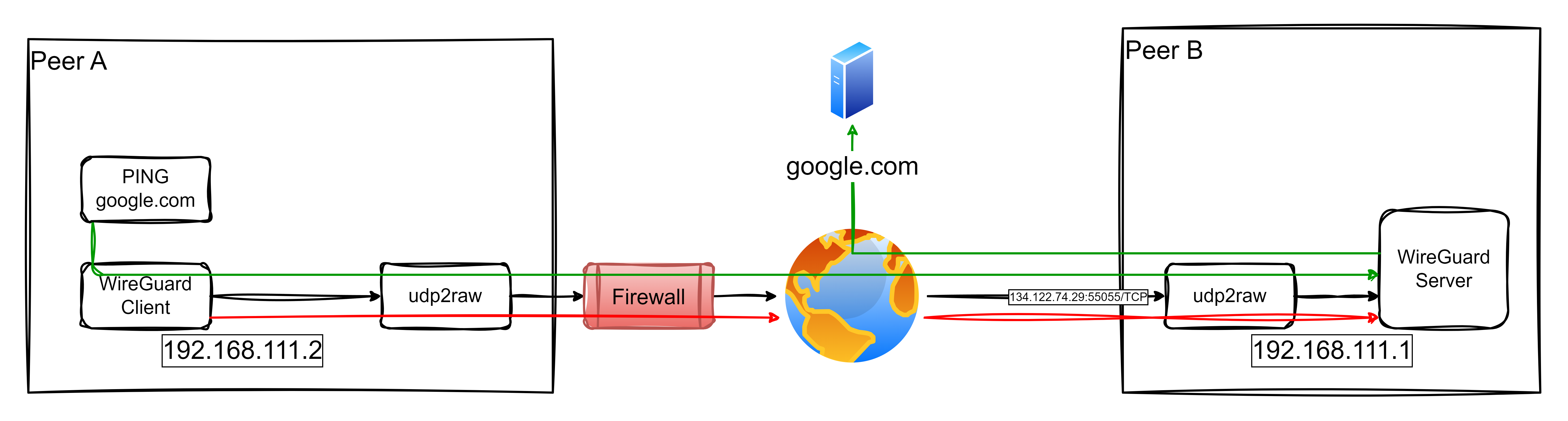
The architecture for this setup is illustrated below:
Install udp2raw, Wireguard and generate keys
cd/tmpwgethttps://github.com/wangyu-/udp2raw/releases/download/20230206.0/udp2raw_binaries.tar.gztarxvfzudp2raw_binaries.tar.gzcpudp2raw_amd64/usr/local/bin/udp2rawrmudp2raw*# based on Ubuntuaptinstallwireguard# we'll work on /etc/wireguardcd/etc/wireguard# generate privatekeywggenkey|sudotee/etc/wireguard/private.keysudochmodgo=/etc/wireguard/private.key# obtain public keysudocat/etc/wireguard/private.key|wgpubkey|sudotee/etc/wireguard/public.key
When eveything is installend and configured, just run in all endpoints next commands:
sudowg-quickupwg0# for status check:wg# udp2raw logs at:tail-f/var/log/udp2raw.log# enable automatic wireward service in Ubuntusudosystemctlenablewg-quick@wg0.service# start and stop service like alwayssudosystemctlstartwg-quick@wg0.servicesudosystemctlstopwg-quick@wg0.servicesudosystemctlstatuswg-quick@wg0.service
Configuration Files
Endpoint A /etc/wireguard/wg0
# local settings for Endpoint A[Interface]PrivateKey=WMUerfcUpSxUlOp1UmaS2uwelnk8AxhAFrlIWpjheWM=Address=192.168.111.1/24ListenPort=51822# receive wg through udp2rawMTU=1342PreUp=udp2raw-s-l167.99.130.97:55055-r127.0.0.1:51822-k"The2password."-a>/var/log/udp2raw.log2>&1&PostDown=killalludp2raw||true# Enable NAT for traffic forwarding (corporate and fallback internet access)PreUp=echo1>/proc/sys/net/ipv4/ip_forward||truePreUp=iptables-tnat-IPOSTROUTING-oeth0-jMASQUERADE||truePreDown=iptables-tnat-DPOSTROUTING-oeth0-jMASQUERADE||true# remote settings for Endpoint B[Peer]PublicKey=XWl8HeAinHlAZTvaCXDlmO9n/CQLg5qH8jmtROK4jBg=AllowedIPs=192.168.111.2/32PersistentKeepalive=120# remote settings for Endpoint C[Peer]PublicKey=I+gi8l9QRe00W8pTpp8CSoIabz/RXXQXwquXj7eKNwU=AllowedIPs=192.168.111.3/32PersistentKeepalive=120
Endpoint B /etc/wireguard/wg0
# Endpoint B[Interface]PrivateKey=+BB3NI2SUYeKcRoPrZE2+Ot5KnLZJBycPzJ17kfbn34=Address=192.168.111.2/24# Route configuration for public IPPreUp=iproutedeldefault||truePreUp=iprouteadd167.99.130.97via10.2.0.1deveth0||truePostDown=iproutedel167.99.130.97via10.2.0.1deveth0||truePostDown=iprouteadddefaultvia10.2.0.1||trueMTU=1342PreUp=udp2raw-c-l127.0.0.1:50001-r167.99.130.97:55055-k"The2password."-a>/var/log/udp2raw.log2>&1&PostDown=killalludp2raw||true# Endpoint A[Peer]PublicKey=z73wM1b7fhMRA8fmeQw4FntRvgJ9JwTdsQHssXHg3DE=Endpoint=127.0.0.1:50001AllowedIPs=0.0.0.0/0PersistentKeepalive=120
Endpoint C /etc/wireguard/wg0
# Endpoint C[Interface]PrivateKey=YCGzsfeed8QumpfE8bdWRheMzBiUsTB7vXj0YVOQQX0=Address=192.168.111.3/24# Route configuration for public IPPreUp=iproutedeldefault||truePreUp=iprouteadd167.99.130.97via10.2.0.1deveth0||truePostDown=iproutedel167.99.130.97via10.2.0.1deveth0||truePostDown=iprouteadddefaultvia10.2.0.1||trueMTU=1342PreUp=udp2raw-c-l127.0.0.1:50001-r167.99.130.97:55055-k"The2password."-a>/var/log/udp2raw.log2>&1&PostDown=killalludp2raw||true# Endpoint A[Peer]PublicKey=z73wM1b7fhMRA8fmeQw4FntRvgJ9JwTdsQHssXHg3DE=Endpoint=127.0.0.1:50001AllowedIPs=0.0.0.0/0PersistentKeepalive=120
In this post, I’ll share how I set up a WireGuard VPN over TCP using udp2raw, which provides secure access to corporate networks and serves as a fallback for internet access when customer networks impose heavy restrictions. Inspired by Pro Custodibus, this solution enables IoT gateways to seamlessly connect to both the company’s internal services and the broader internet under constrained conditions.
Scenario Overview
The architecture for this setup is illustrated below:
Key Features of the Solution:
Access to Corporate Networks: IoT Gateways securely connect to the corporate network for accessing internal services.
Fallback Internet Access: When the customer’s network restricts internet access but allows TCP connections to the company infrastructure, the IoT Gateway routes its internet traffic through the company’s network.
How It Works:
Endpoint A (Client): An IoT Gateway connects through the restrictive customer network.
Endpoint B (Server): The WireGuard server is accessible via a public IP (134.122.74.29) on TCP port 55055.
Traffic flows through a TCP tunnel created with udp2raw, enabling the gateway to securely access the corporate network or relay internet traffic via the company’s infrastructure.
This dual-purpose setup ensures robust connectivity for IoT devices even in challenging environments.
Video Demonstration (in Spanish)
I’ve created a video demonstration in Spanish showcasing the entire setup and functionality of this scenario. The video walks through the following steps:
Explaining the problem and network constraints.
Demonstrating the configuration of both endpoints (client and server).
Showing the connection initiation and testing, including how traffic flows through the VPN tunnel.
Verifying fallback internet access through the company network.
This video is ideal for those who prefer visual explanations or need extra guidance in implementing this solution.
Configuration Files
1. Endpoint B (server, /etc/wireguard/wg0.conf)
This configuration allows Endpoint B to act as a gateway for both corporate access and fallback internet connectivity:
# local settings for Endpoint B[Interface]PrivateKey=EMqyADu4Xeu95ZpNZE97FET5eKzN1WSwBkeBWtX1yGg=Address= 192.168.111.1/32ListenPort= 51822# receive wg through udp2rawMTU= 1342PreUp= udp2raw -s -l 134.122.74.29:55055 -r 127.0.0.1:51822 -k "The2password." -a >/var/log/udp2raw.log 2>&1 &PostDown= killall udp2raw || true# Enable NAT for traffic forwarding (corporate and fallback internet access)PreUp= echo 1 > /proc/sys/net/ipv4/ip_forward || truePreUp= iptables -t nat -I POSTROUTING -o eth0 -j MASQUERADE || truePreDown= iptables -t nat -D POSTROUTING -o eth0 -j MASQUERADE || true# remote settings for Endpoint A[Peer]PublicKey=Xt70DJy8ldPcDNW4YM2Dt94n16pTQKFxhmvpgKvJyng=AllowedIPs= 192.168.111.2/32PersistentKeepalive= 120
Key Points:
NAT Rules: These rules enable traffic originating from Endpoint A to use Endpoint B for accessing the internet.
MTU Adjustment: The MTU is set to 1342 to prevent fragmentation issues over the TCP tunnel.
Assumptions:
eth0, is the name of the interface for reaching Internet.
192.168.111.0/24 is available for point-to-point connections in the tunnels.
ud2raw is in PATH.
Don’t re-use my pub and private keys. Neither the pre-shared key of used by udp2raw.
Endpoint A (client, /etc/wireguard/wg0.conf)
This configuration sets up Endpoint A to route all traffic (corporate and internet) through Endpoint B:
[Interface]PrivateKey=yAxByb468bAuMdg5S6AlfYkxbeYDOMEKxdaJ7d2p83g=Address= 192.168.111.2/32# Route configuration for public IPPreUp= ip route del default || truePreUp= ip route add 134.122.74.29 via 10.2.0.1 dev eth0 || truePostDown= ip route del 134.122.74.29 via 10.2.0.1 dev eth0 || truePostDown= ip route add default via 10.2.0.1 || trueMTU= 1342PreUp= udp2raw -c -l 127.0.0.1:50001 -r 134.122.74.29:55055 -k "The2password." -a >/var/log/udp2raw.log 2>&1 &PostDown= killall udp2raw || true[Peer]PublicKey= VUN2JqZiGQ1V46PDoFECw/nMs3/o6n8PvGMV+ad+Hww=Endpoint= 127.0.0.1:50001AllowedIPs= 0.0.0.0/0PersistentKeepalive= 120
Key Points:
Fallback Internet Routing: The AllowedIPs = 0.0.0.0/0 directive ensures all traffic is routed through Endpoint B, including internet traffic.
Dynamic Route Adjustments: The PreUp and PostDown commands manage routes for efficient fallback connectivity.
Here’s the improved Implementation Steps section based on your feedback and expertise in WireGuard and udp2raw:
Implementation Steps
This section outlines the precise steps required to set up the WireGuard VPN over TCP using udp2raw. Follow these instructions carefully for both Endpoint A (client) and Endpoint B (server).
1. Pre-requisites
WireGuard Installation: Ensure WireGuard is installed on both systems. This can usually be done via the package manager of your operating system (e.g., apt install wireguard for Debian-based distributions).
udp2raw Binary: Download the appropriate udp2raw binary from its GitHub Releases Page. Binaries are available for various architectures. For simplicity:
Extract the binary from the tarball (e.g., udp2raw_amd64 for most x86_64 systems).
Place the binary in a directory accessible from your PATH (e.g., /usr/local/bin).
Verify the installation: which udp2raw udp2raw -h # Should display the help menu
2. Prepare the Configuration Files
The configuration files should be located at /etc/wireguard/wg0.conf. Each endpoint has its own specific configuration:
Endpoint A: Use the wg0.conf provided earlier, replacing placeholders like keys and IPs as needed.
Endpoint B: Use the wg0.conf provided earlier.
Ensure both files reflect the IP addresses, MTU settings, and public/private keys accurately.
3. Generate WireGuard Keys
WireGuard requires public-private key pairs for secure communication. Generate them as follows:
Generate the Private Key: wg genkey > privatekey
Generate the Public Key from the private key: cat privatekey | wg pubkey > publickey
Place the private key in the [Interface] section of the respective configuration file (PrivateKey = ...) and the corresponding public key of the peer in the [Peer] section (PublicKey = ...).
Note: Never share your private keys.
4. Start the VPN Tunnel
Start the Server First (Endpoint B):
Bring up the WireGuard interface using wg-quick: sudo wg-quick up wg0
Verify that the interface is active: wg show
Start the Client (Endpoint A):
Bring up the client WireGuard interface: sudo wg-quick up wg0
Verify that the interface is active: wg show
5. Test the Connection
Once both endpoints are active, initiate traffic from Endpoint A to Endpoint B. This step ensures the udp2raw TCP socket is properly established and functioning:
If the ping succeeds, the connection is working as expected.
If it fails, check the logs for udp2raw and WireGuard on both endpoints for errors: less /var/log/udp2raw.log
Once the initial handshake completes, the tunnel will remain active as long as PersistentKeepalive is configured in the client configuration (e.g., PersistentKeepalive = 120).
6. Validate Fallback Internet Access
To confirm the fallback internet routing through Endpoint B:
On Endpoint A, run a test to confirm external connectivity: curl -I https://www.google.com
If the response headers are received, the internet routing through Endpoint B is functioning.
Verify that the traffic is routed through the WireGuard tunnel: traceroute google.com
If fallback internet access fails, ensure that NAT is correctly configured on Endpoint B: iptables -t nat -L -n
7. Troubleshooting
Log Files:
Check the udp2raw logs on both endpoints for issues (e.g., MTU mismatches, handshake failures).
Review WireGuard logs for additional details.
MTU Issues:
If large packets fail but small packets (e.g., ping) succeed, reduce the MTU (e.g., to 1280).
8. Automate Startup
To ensure the VPN starts automatically on boot:
Enable the WireGuard service: sudo systemctl enable wg-quick@wg0
Add udp2raw commands to a systemd service or the PreUp directive in wg0.conf (as shown in the configuration files).
With these steps, you now have a fully operational WireGuard tunnel over TCP, enabling secure communication between endpoints and fallback internet connectivity via the company’s infrastructure.
Conclusion
This configuration provides a robust solution for IoT Gateways operating in restrictive environments. By leveraging udp2raw, WireGuard traffic is tunneled over TCP, enabling:
Seamless Corporate Access.
Fallback Internet Connectivity through the company network when customer environments impose constraints.
This versatile setup ensures uninterrupted operations and secure communications for IoT devices. Explore the Pro Custodibus guide and udp2raw GitHub repository for additional insights.
Amb httptunnel es poden establir connexions TCP sobre un enllaç HTTP, és a dir, disposem de dues eines el htc i el hts, escencialment el que fa és:
hts: publica un port simulant un servidor HTTP al conectar-hi amb htc ens enviarà cap al HOST:PORT configurats
htc: es conecta a hts usant HTTP i simulant un client HTTP normal (ffx, crhome, ie, etc) però en realitat transporta paquets TCP en el payload de les queries, l’usuari pot conectar-se a un port local que es publica i que permet accedir al HOST:PORT al que ha conectat hts de forma transparent
Per fer una prova de concepte jo el que he fet és conectar el hts amb un servidor VNC, al costat del htc he connectat un client VNC i he accedit al VNC de forma totalment transparent, a més amb un sniffer he comprovat que els paquets que passeben per la xarxa eren paquets HTTP estàndards, i així era. Tan senzill com això:
A més també suporta la possibilitat de fer-ho a través d’un proxy, això si aquest només esta suportat si és sense autenticació o amb autenticació bàsica. Així doncs, a partir d’això em venen al cap algunes millores interessants:
suportar autenticació Digest i NTLM.
permetre accés al tunel via stdin/stdout (així ho podriem usar amb SSH com a ProxyCommand).
poder connectar-se a un segon proxy en l’extrem remot, és a dir, hts no té l’enllaç pre-establert.
suportar SSL, així ens estalbiariem haver d’usar stunnel per simular HTTPs.
Una altre d’aquelles eines que malgrat ser petitones i rares poden servir per fer mil i una coses. Per exemple, connectar a un servidor DNS a través d’un port TCP en una xarxa on el tràfic UDP estigui tancat.
UDPTunnel és una eina molt simple d’usar i la seva sintaxis és molt autoexplicativa:
és interessant fixar-se que el mateix executable pot ser usat com a servidor o com a client, així doncs ideal per construir els dos costats de l’enllaç de forma simple. A més si ho combinem amb httptunnel podem passar per sobre de proxies de forma senzilla.
La idea es força simple es tracta de transportar un fluxe TCP sobre d’una connexió HTTP convencional, fiexeu-vos que en aquest cas no estem parlant de proxies ni similars. Sinó de paquets TCP+HTTP que en la part de dades del HTTP tornen a implementar TCP, si fessim un petit esquema seria algo així:
+----+----+------+------+-----+------+
|... | IP | TCP | HTTP | TCP | DATA |
+----+----+------+------+-----+------+
Si realment teniu aquest interés montar reDuh és realment senzill, de fet, suporta servidors amb JSP, PHP i ASP. En escència l’únic que fa és usar aquests protocols per re-obrir una connexió TCP. Així doncs, al servidor on montem aquesta eina hem de tenir certs privilegis per poder obrir sockets des d’un script.
L’eina no és massa recomanable si pensem tenir fluxes de dades molt intensos, per exemple, senssions VNC. Però funciona prou bé si el que volem és transportar una sessió SSH o similar.
Reading time: < 1 minute
A pesar de que la solución se alcanzó y aplico durante los meses de agosto y septiembre, hasta hoy no he podido grabar la solución en este podcast. Espero que haya sabido explicarla bien y que quede claro como se ha hecho para solucionar el problema, sinó preguntad.
Al projecte GATv2 fa un parell de dies que hi he publicat un subprojecte que anomeno tcp-fwd. Es tracta d’un petit i simple aplicatiu programat amb Python i Twisted. La funcionalitat és molt senzilla es tracta d’un bouncer TCP que en cas de no poder connectar amb el primer destí on re-enviar el tràfic TCP ho prova amb el segon, sinó el tercer i així fins a tants servidors com s’hagin definit. Si no es pot acabar establint la connexió es desconnecta l’enllaç TCP cap al bouncer. O sigui, el comportament és transparent pel client original. Pels que no estigueu familiaritzats amb la funcionalitat d’un bouncer la intentaré explicar. Es tracta d’un socket TCP que escolta en un port i actua com un reverse proxy. O sigui, quan rep una connexió acte seguis s’obre una altre connexió cap al servidor i si aquesta es pot establir llavors connecta la primera connexió amb la segona.
L’inconvenient més gran que veig en aquesta idea és que la connexió que arriba al servidor final no té com a origien la IP del client, sinó la IP del servidor que fa de bouncer això fa que el fitxer de logs del servidor final no tingui la informació IP del client que realment s’ha connectat. Malgrat axiò hi ha escenaris en que aquesta eina és molt útil, ja que no sempre el més important són aquests logs sinó que el client acaba obtenint el servei que volia de forma trasparent i el sistema de failover que uso sempre segueix la mateixa seqüència de prova i error per cada socket que s’obre, així doncs, el sistema de failover és instantani i no perd ni una sola crida.
Una de les aplicacions per les que l’estic usant és per fer l’entrega de correu a un postfix. Es tracta d’un servidor de correu que només fa filtratge de correu i els correus que passen els filtres s’entreguen al servidor de correu real de l’empresa, doncs bé, per saber quin és el servidor de l’empresa uso el fitxer de configuració /etc/postfix/transport on s’indica segons el domini el servidor on entregar el correu. Però no he sabut veure com dir-li més d’un servidor de correu on fer l’entrega. Així doncs, el que faig és posar com a IP i port de transport una IP localhost i un port al atzar, llavors el postfix entrega el correu al bouncer situat en aquesta IP localhost i és el bouncer que intenta connectar aquest socket amb algún dels servidors de correu interns. Per tant, el tema és completament transparent pel postfix i els servidors que reben el correu tenen la mateixa IP origen que si ho haguessin rebut directament del postfix.
Suposo que la idea ha quedat ben definida, sinó ja sabeu que podeu fer-me les preguntes que calguin. El codi del projecte el teniu a: tcp-fwd.